I got a dynamo hub for my bike and a fancy headlight. It's sweet, but I'm discovering that there're no standards for making tail lights work, so I just had to do some light reverse-engineering and soldering. And this is the findings.
Different manufacturers do tail lights differently. Most tail lights are not connected directly to the dynamo, but to the headlight instead. Busch+Müller tail lights take an AC signal that looks very similar to what the hub is producing. You're not supposed to hook it up to the hub directly, but it does appear to work, and it's not clear how the headlight's tail-light output is different from the hub input. I haven't scoped it.
Supernova tail lights work differently. Some guy on the internet reverse-engineered the headlight circuit showing an LM317 regulator producing 5.9V for the tail light. I have a Supernova E3 tail light (original one; model E161). The case says "6V", which is close to the 5.9V they give it. It wants its 6V, but I don't have a Supernova headlight, so I don't have 6V to give it. I do have a USB charger, so I have 5V instead. Giving it 5V does appear to work, but that results in less brightness than I would like. Presumably the voltage difference is to blame?
I took apart the tail light. The circuitry is encased in hot glue. Scraping that off, we can see the action:
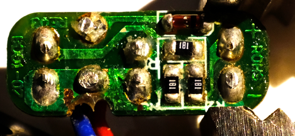
The circuit looks like this:

More or less, this is as expected. The circuit was designed to receive 6V, so the resistances (180 ohms) were selected to produce a certain amount of current. Given 5V, there's less current and less brightness. I can fix this by reducing the amount of resistance to bring the current levels up. I hooked up a power supply to produce 5V and 5.9V, and I measured the voltages in the circuit in those two states. Assume little accuracy in all of this
| 5V | 5.9V | |
|---|---|---|
| V across input diode | 0.8V | 0.8V |
| V across the resistors | 2.37V | 3.25V |
| V across the LEDs | 1.83V | 1.85V |
As expected, the voltages across the diodes are stable, and the resistors see the bulk of the voltage difference. The circuit designers wanted 3.25/180 ~ 18mA. With my reduced voltage I was getting 2.37/180 ~ 13mA instead. So I was 28% less bright than I should have been. That doesn't sound like a lot, but it's hard to tell by just looking at the thing.
In any case, I can reduce the resistances to get the higher current at 5V: I want a resistance R of 180/3.25*2.37 ~ 131 ohms. In the interest of doing less work, I simply added more resistors in parallel instead of replacing the existing ones. So I need to add in parallel a resistance R such that 180R/(180+R) = 131. So I want a parallel R ~ 485 ohms. Looking through my box of parts, I don't have any nice surface-mount resistors with anywhere near the right resistance. But I do have through-hole ones at 470 ohms. Close-enough. I did some soldering gymnastics:
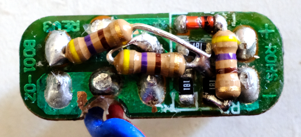
And I'm done. Haven't done any night rides outside yet with this setup, but in theory this should be bright-enough. And since the resistors are just burning off the excess voltage, and I'm giving it less voltage to burn off, I'm being more efficient than I would have been with 6V and the stock resistors.